Post by dieseldoc on Jun 21, 2008 2:09:14 GMT -5
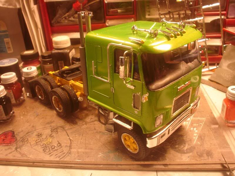
AMT Mack R685ST Kit # 38683
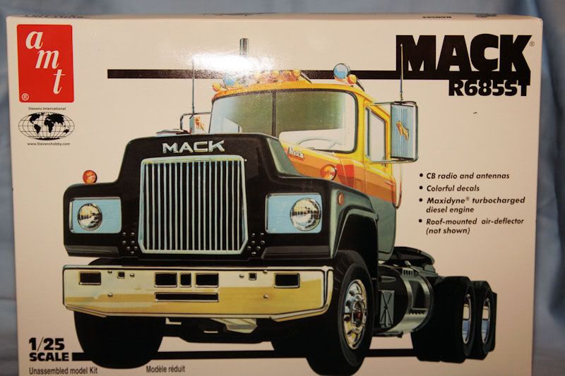
I picked up my reissue of this kit from Model Empire ( www.modelempire.com ) for $39.99. Once I got home I was able to examine the kit content to see what it has to offer. Follow along as I build this kit.
The kit is packaged in the typical AMT fashion with 5 bags containing over 250 parts two of which are chrome. Also included is a well render decal sheet consisting of cab stripes and Illinois license plates. The instructions consist of 2 pages with 28 steps in the build sequence.
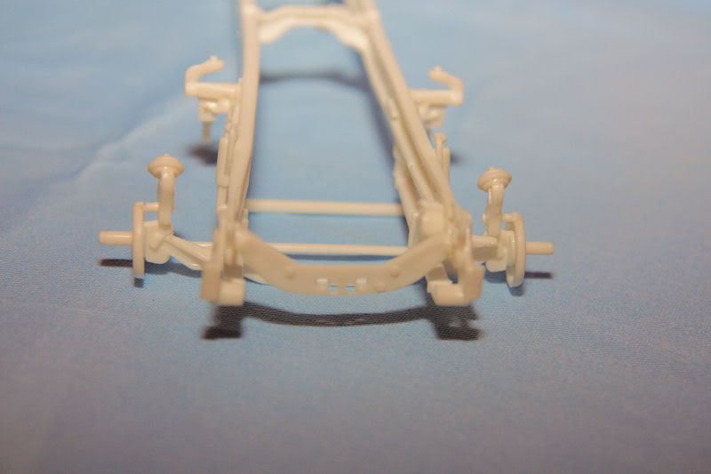
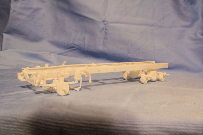
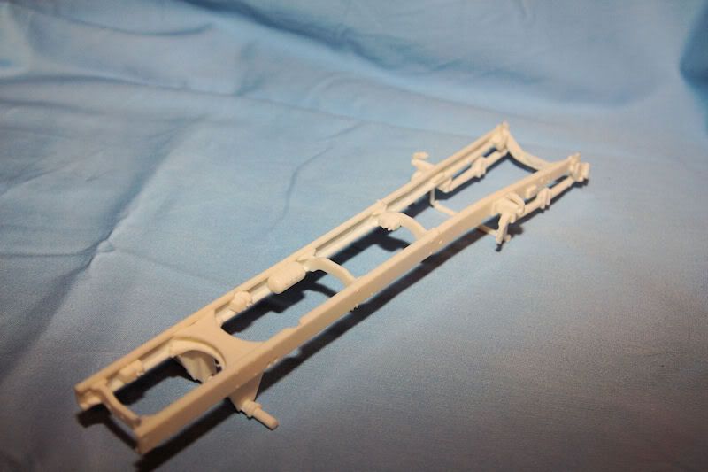
I chose to start this build with step #8 the frame. While gathering the frame rails and cross members from the sprue I found that the part numbers called out on the instruction sheet do not match the lightly engraved numbers on the sprue. With that said keep the sheet two handy with the parts lay out on them handy through out the course of this build. Next while test fitting the cross members to the frame rail I found that at each cross member locating point on the frame rail there is an ejector pin stub. These will have to be removed for proper assembly of the frame. My tool of choice for this was a small chisel and even by using the chisel I still proceeded cautiously so I would not damage the frame rail flanges. With the stubs removed assembly of the frame proceeded as expected until I got to the front cross member. When installing the front cross member proceed cautiously as the locating marks are not as positive as they are for the other four cross members. I also found that it was a bit fiddly to keep this cross member vertical while the glue set up. I assembled parts 46,47,48 and 49 prior to mounting them onto the frame. While the glue was setting I assembled parts 50 and 51. Do not remove the pins that stick up off of part # 50. These aid in locating this cross bar onto the frame.
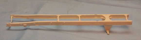
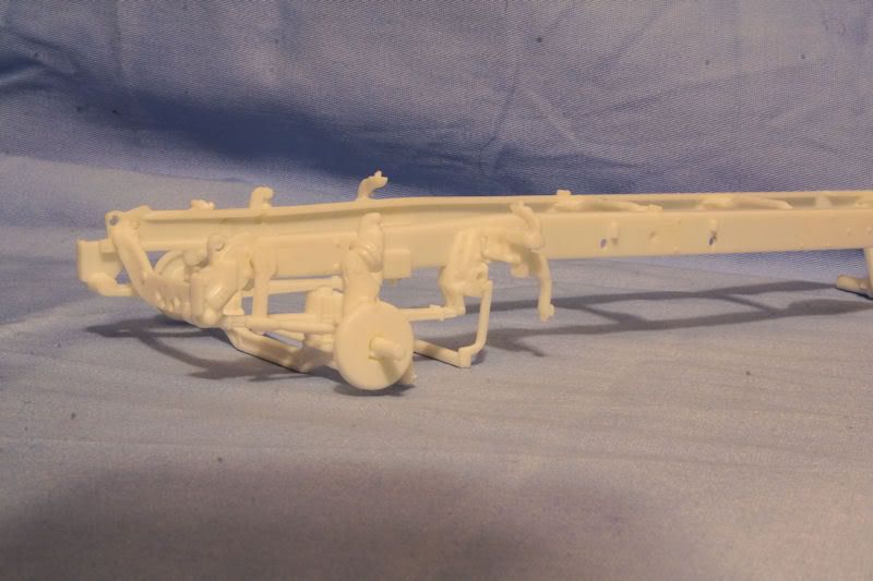
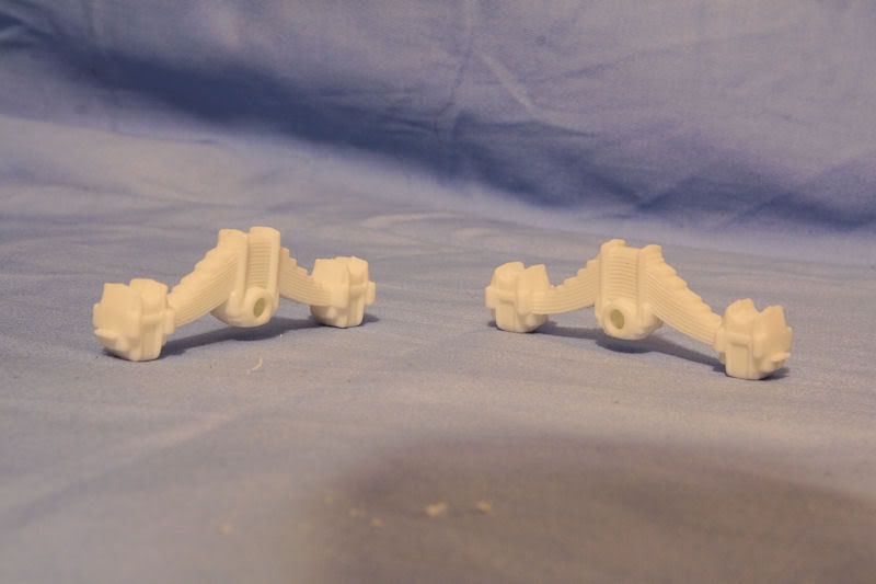
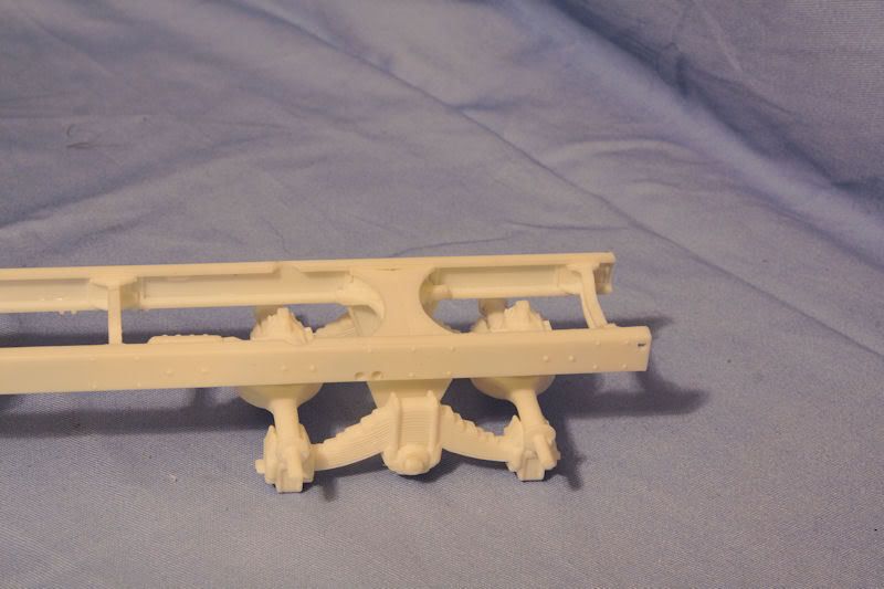
Moving on to step #9 I started by assembling parts 58 and 59 the air tank. On the sprue there are two of each part # 58 and # 59. As far as I can tell at this point after reviewing the instructions again we will only be using one of each. This air tank has some pretty nice detail when it comes too the air line ports. These should really aid the super detailer in adding air lines to the model. While the glue set up I clean up and installed the front spring assemblies. On the sprue there are 3 of part # 55. Step 9 calls out for using two of them. Since the third is installed later in step 10, I went and installed it now. Part # 54 appears to be a frame mounted fuel filter and header assembly. I did not install this on the frame now but will install it later after the frame is given its black base coat and the filter is detail painted.

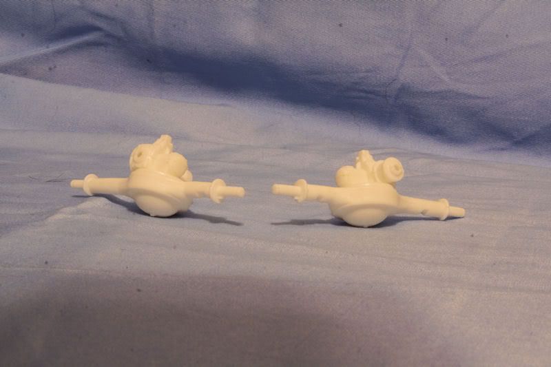
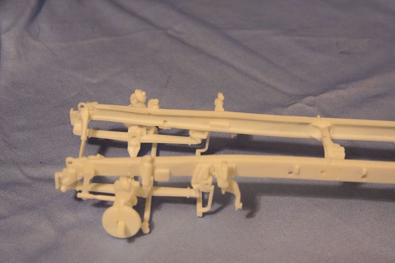
Continuing on with step # 10 I will not install parts 60 and 61 until later when I know when and where part 60 connect too later. This will save me the possibility of alignment issues later in the build. When installing part # 63 be careful as there are 2 part # 63’s but they are different. There is a left and a right side. The difference is the front edge and how they are notched out. The left side has a square notch and the right side has a triangular notch in it. Parts 62 and 206 that the instructions call out look totally different than what they have pictured so don’t use the drawing as a reference when hunting through the parts trees for these parts.
I picked up my reissue of this kit from Model Empire ( www.modelempire.com ) for $39.99. Once I got home I was able to examine the kit content to see what it has to offer. Follow along as I build this kit.
The kit is packaged in the typical AMT fashion with 5 bags containing over 250 parts two of which are chrome. Also included is a well render decal sheet consisting of cab stripes and Illinois license plates. The instructions consist of 2 pages with 28 steps in the build sequence.
I chose to start this build with step #8 the frame. While gathering the frame rails and cross members from the sprue I found that the part numbers called out on the instruction sheet do not match the lightly engraved numbers on the sprue. With that said keep the sheet two handy with the parts lay out on them handy through out the course of this build. Next while test fitting the cross members to the frame rail I found that at each cross member locating point on the frame rail there is an ejector pin stub. These will have to be removed for proper assembly of the frame. My tool of choice for this was a small chisel and even by using the chisel I still proceeded cautiously so I would not damage the frame rail flanges. With the stubs removed assembly of the frame proceeded as expected until I got to the front cross member. When installing the front cross member proceed cautiously as the locating marks are not as positive as they are for the other four cross members. I also found that it was a bit fiddly to keep this cross member vertical while the glue set up. I assembled parts 46,47,48 and 49 prior to mounting them onto the frame. While the glue was setting I assembled parts 50 and 51. Do not remove the pins that stick up off of part # 50. These aid in locating this cross bar onto the frame.
Moving on to step #9 I started by assembling parts 58 and 59 the air tank. On the sprue there are two of each part # 58 and # 59. As far as I can tell at this point after reviewing the instructions again we will only be using one of each. This air tank has some pretty nice detail when it comes too the air line ports. These should really aid the super detailer in adding air lines to the model. While the glue set up I clean up and installed the front spring assemblies. On the sprue there are 3 of part # 55. Step 9 calls out for using two of them. Since the third is installed later in step 10, I went and installed it now. Part # 54 appears to be a frame mounted fuel filter and header assembly. I did not install this on the frame now but will install it later after the frame is given its black base coat and the filter is detail painted.
Continuing on with step # 10 I will not install parts 60 and 61 until later when I know when and where part 60 connect too later. This will save me the possibility of alignment issues later in the build. When installing part # 63 be careful as there are 2 part # 63’s but they are different. There is a left and a right side. The difference is the front edge and how they are notched out. The left side has a square notch and the right side has a triangular notch in it. Parts 62 and 206 that the instructions call out look totally different than what they have pictured so don’t use the drawing as a reference when hunting through the parts trees for these parts.